|
|
The following information is provided to
help understand some of the terms and other
descriptions of parts and related items about
American Flyer Trains.
RFG also prints several booklets and manuals,
that have more detailed information.  M3103 M3103
Go toOperating Books, Manualsfor more information.
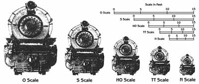
THE BASICS
"S", "O" & "HO"
Gauge
Gilbert American Flyer Trains were made in
3 gauges. When they were manufactured by
The American Flyer Manufacturing Company,
they were made in Standard Gauge and a version
of "O" gauge. "O" Gauge
is what Lionel is today, along with "O27".
They run on three rail track.
The most popular size of Gilbert American
Flyer Gauges is "S Gauge", which
runs on two rail track and is scaled 3/16"
to the foot. Slightly smaller than "O"
Gauge which is 1/4" to the foot. Gilbert
American Flyer was also made in "HO"
(Half "O") or approximatly 1/8"
to the foot. Gilbert also produced it's "O"
Gauge line in a scaled "O" Gauge
of 3/16" to the foot.
AC or DC Electric Current?
Most American Flyer "S Gauge" and
"O" engines were designed to run
on AC or Alternating Current. Although, the
motors are what is referred to as "series
wound", so they can also operated on
DC or Direct Current. Maximum voltage is
15 to 17 volts.
American Flyer engines also were made that
would only run on DC, those engines have
a "DC" after the engine number.
Engines that have an "AC", after
the engine number will run on both.
All American Flyer Transformers are AC. The
DC versions are called Rectaformers.
Early American Flyer "HO" engines
ran on AC, while later versions run on DC.
In general the power units for the HO are
called DC power packs.
Connecting Power to the Track
"S" & "O"
The power from the transformer is connect
to the track with the use of a Power Terminal.

690 American Flyer "S" Kit w/wires
& Instructions
707 American Flyer - single contact "S"
"HO" uses a special track section
to connect the power.
American Flyer "S", COUPLERS
There are three major types of couplers:
Link Couplers were used from 1946 till 1952.
They are the long black plastic shank with
a sort of hook on the end. They may or may
not have a black or brass round weight on
the side.
Knuckle Couplers were introduced in 1952.
They resemble real American style couplers
and look like a fist. They have a working
jaw or knuckle. There are two types of Knuckle
Coupler.
The conversions type is used to convert Link
Coupler equipment to Knuckle Coupler, they
have a slot in the shaft. 
Originally equipped Knuckle Couplers, have
either a hole or a solid shaft.
Pikemaster couplers look similar to Knuckle
Couplers, however they are part of the truck
assembly, and have no moving parts. They
are not repairable or replaceable.
There is also a nonoperating Knuckle Coupler
that was used on some inexpensive sets.
AMERICAN FLYER "S Gauge", STEAM
ENGINE
BRUSHES and SPRINGS
There are several variations of Brushes and
Springs used from 1946 to 1966. In 1946/47
the motor brush bracket used round brushes
(58A) with a slot and a lever type spring
(71A). In 1948, a round brush with a smaller
diameter shoulder (58) and a coil spring
(71), began to be used.
There are several engines with the same model
number, that use different brushes and springs.
AMERICAN FLYER "S Gauge", NUMBERING
SYSTEM
American Flyer cars, engines and accessories
all were designated by an item number. In
the "S" gauge line, early accessories,
1946-1959, carried a 3 digit number, starting
with either a 5 or a 7. Most of the ones
with a 5, a carry over from the pre WWII,
"O" gauge line. The item numbers
did not appear on the accessory itself.
Steam engines from 1946 to 1959, have 3 digits,
beginning with a 2 or a 3. This number was
stamped on the side of the engine, under
the cab window, were the engineer would sit.
Diesel engines from 1950 to 1959, have a
3 digit number, beginning with 3 or 4. Not
all had the numbers on the side.
Cars from 1946 to 1952, have 3 digit numbers.
They either begin with a 6 or a 7. And one
set of passenger cars that begin with a 5.
The 7 was used on operating cars. These cars
are for the most part equipped with link
couplers. In 1953, with the introduction
of Knuckle Couplers, the numbers were changed
to begin with a 9. There are also some inexpensive
cars with numbers beginning with 8.
In 1959 a new 5 digit numbering system was
started, with all items starting with a 2.
There are differences in manufacture for
items with a 5 digit number from those same
items with a 3 digit number. That is why
some parts have a notation (5 digit).
American Flyer SMOKE UNITS
American Flyer had four types of Smoke and
Choo Choo Units. The first type was introduced
in 1946, it is the Smoke in Tender type,
and denoted by S.I.T. The smoke unit is in
the tender, or what some people refer to
as the coal car, behind the engine.
The second type is a Smoke in Boiler unit.
It is in the boiler or main part of a steam
engine. It was used on the majority of steam
locomotives. There are 2 versions, the early
version has two chambers, an upper and lower.
The later version has only one chamber were
the smoke wick and coil are located.
The third type is also a boiler mounted unit,
but is smaller and used in the Docksider
and Franklin and Washington engines, and
also the HO engines.
The forth type, also a boiler mounted unit,
was used on the Casey Jones style, Southern
engine.
All types were designed to use a liquid smoke
fluid. The fluid was sold in either small
soft red ampules or bottles.
Unlike Lionel, American Flyer never used
smoke pellets.
RFG has Original Formula Smoke Fluid @ 2
oz. 
American Flyer Horn and Whistle units
There are two basic American Flyer Horn or
Whistle units. All the steam and diesel engines
that had horns or airchime whistles, except
for the model 314AW, were about the same.
They all require a special activation unit.
The activation units must be wired to the
track.
The 314AW has a Lionel type whistle, it also
requires an activation unit.
|